Page 2 of 7 FirstFirst 1234 ... LastLast
Results 26 to 50 of 154

Thread: The Fear Monger

  1. #26


    Array
    Status
    Offline
    Join Date
    03-16-2011
    Posts
    3,823
    Location

    Sacramento, CA
    Vehicle

    1979 Dodge D-50
    Engine

    Chevy V6
    I might change the build name to: The Greenhouse Monster.
    (just in case you need a "TIP" for them in the contest located in the paint booth).
    I even found one strange rap song. That could help you or confuse you.

    All I can say is Wow.


    Oh and the other truck is going to be converted into a street rally style D-50. Full cage time again.
    Last edited by camoit; 04-27-2011 at 04:51 PM.
    Members come and members go, But the board keeps track of them.
    Find me on FaceBook
    clicking HERE.

    Or look on YouTube Click Here.
    http://mobilemillwright.com

  2. #27


    Array
    Status
    Offline
    Join Date
    03-21-2011
    Posts
    767
    Location

    WA
    Vehicle

    1989 Mitsubishi Mighty Max
    Engine

    4G63-T
    Alright. So you are going to keep the camo d50 then?

  3. #28


    Array
    Status
    Offline
    Join Date
    03-16-2011
    Posts
    3,823
    Location

    Sacramento, CA
    Vehicle

    1979 Dodge D-50
    Engine

    Chevy V6
    Quote Originally Posted by 4doorciv View Post
    Alright. So you are going to keep the camo d50 then?

    The body style yes.
    Members come and members go, But the board keeps track of them.
    Find me on FaceBook
    clicking HERE.

    Or look on YouTube Click Here.
    http://mobilemillwright.com

  4. #29


    Array
    Status
    Offline
    Join Date
    03-16-2011
    Posts
    3,823
    Location

    Sacramento, CA
    Vehicle

    1979 Dodge D-50
    Engine

    Chevy V6

    Ceramic & Powder Coating

    Today we are going to cover Ceramic coatings on an exhaust system.
    As the majority of you mechanics know that the exhaust is one of the worst things to work on. It is rusted and will not come apart no matter what you use. It’s just something we all hate. But there is a way to make it last for years. Ceramic Coating can do just that.
    I used a place called AIC.


    And yes that is me in the video on the front page. You can read more about Ceramic Coating and Powder Coating on their site. http://www.amerikotecoatings.com I had them Ceramic Coat my exhaust system. Since I was going to wrap the exhaust, I wanted to protect the headers and pipes as best as I could. AIC coats everything, from the fence to sprint car frames.
    The first step is to sand blast your parts.


    2.JPG

    Next they will bake all the moisture out of the part. After the first bake they coat the part. Ceramic is a liquid that is sprayed on using a HVLP gun.


    Then the parts are baked one more time. They can even make the finish have a gloss look to it. Powder Coating is a dry coat that is electro static and uses a special gun to charge the powder. It is also a thicker coating then Ceramic.


    If you get something coated do your self a favor, look at the colors they have available. The guys that work with your parts are board of the color Black. They see it all the time and will tell you the same thing. There is more then one color in the world, and we are sick of black.

    6.JPG 7.jpg
    Members come and members go, But the board keeps track of them.
    Find me on FaceBook
    clicking HERE.

    Or look on YouTube Click Here.
    http://mobilemillwright.com

  5. #30


    Array
    Status
    Offline
    Join Date
    03-16-2011
    Posts
    3,823
    Location

    Sacramento, CA
    Vehicle

    1979 Dodge D-50
    Engine

    Chevy V6

    Time for a small update.

    I finally installed the secondary suspension, or Bump stops, as they are known. They are Fox 2.5 X 4 inch Air Bump stops. They can be charged to 500 PSI.


    DSCN3637.JPG DSCN3639.jpg


    At the same time I built the removable cross beam that stops the upper shock towers from moving. I used a ¾” bolt. I welded the nut inside of the cross bar. Then used a peace of 1” X ¼” wall DOM tubing. This gives me a tight fit for the bolt and a way to keep from crushing the shock tower tubing.


    DSCN3649.JPG DSCN3658.JPG


    I started working on the electrical system. I’m doing things the old fashion way. With no solder less connectors. All splices and ends are solder are heat shrink sealed.


    The only connectors used are the water tight and fully sealed GM style. They are a 3-peace type connector.


    DSCN3694.JPG DSCN3700.JPG


    The fuse panel is out of a Freightliner truck. It has circuit breakers not fuses. This way if there is a problem then the power can be restored automatically with out the use of a fuse.

    Last edited by camoit; 02-25-2012 at 12:00 AM.
    Members come and members go, But the board keeps track of them.
    Find me on FaceBook
    clicking HERE.

    Or look on YouTube Click Here.
    http://mobilemillwright.com

  6. #31

    Array
    Status
    Offline
    Join Date
    03-26-2011
    Posts
    409
    Location

    Portland, OR
    Vehicle

    1986 Dodge Power Ram 50
    Engine

    G54B
    Awesome idea on the breakers...something I should consider. Pain in the ass to hit up a large sagebrush or jack rabbit for a spare fuse...Freight Shaker is a local company, mebbe I should give em a call.

    Need a real fuse BOX anyway, just have a couple of bare panels stuck in my foot well at the moment.

  7. #32


    Array
    Status
    Offline
    Join Date
    03-16-2011
    Posts
    3,823
    Location

    Sacramento, CA
    Vehicle

    1979 Dodge D-50
    Engine

    Chevy V6
    Quote Originally Posted by Acuta73 View Post
    Awesome idea on the breakers...something I should consider. Pain in the ass to hit up a large sagebrush or jack rabbit for a spare fuse...Freight Shaker is a local company, maybe I should give em a call.

    Need a real fuse BOX anyway, just have a couple of bare panels stuck in my foot well at the moment.
    Go to a big rig wreaking yard. If I was to get them new then it would cost some where around $200 just for the breakers.
    Members come and members go, But the board keeps track of them.
    Find me on FaceBook
    clicking HERE.

    Or look on YouTube Click Here.
    http://mobilemillwright.com

  8. #33


    Array
    Status
    Offline
    Join Date
    03-21-2011
    Posts
    767
    Location

    WA
    Vehicle

    1989 Mitsubishi Mighty Max
    Engine

    4G63-T
    Wow. I need some kind of fabrication skills. That rat rod looks awesome. I wonder how it'll look and drive with a 4g63 powering it....... Did you make that bar replaceable as you use the truck for jumps? I know with a few high jumps itll tweak like crazy.

  9. #34


    Array
    Status
    Offline
    Join Date
    03-16-2011
    Posts
    3,823
    Location

    Sacramento, CA
    Vehicle

    1979 Dodge D-50
    Engine

    Chevy V6
    Quote Originally Posted by 4doorciv View Post
    Wow. I need some kind of fabrication skills. That rat rod looks awesome. I wonder how it'll look and drive with a 4g63 powering it....... Did you make that bar replaceable as you use the truck for jumps? I know with a few high jumps itll tweak like crazy.
    If I bend it the truck is pretty much a total loss. It's 0.120 wall. The only way to bend it is to crash it, HARD...
    Members come and members go, But the board keeps track of them.
    Find me on FaceBook
    clicking HERE.

    Or look on YouTube Click Here.
    http://mobilemillwright.com

  10. #35


    Array
    Status
    Offline
    Join Date
    03-16-2011
    Posts
    3,823
    Location

    Sacramento, CA
    Vehicle

    1979 Dodge D-50
    Engine

    Chevy V6

    Body construction has begun.

    The bodywork is under way.
    The first step was to set the body on the truck and look at what was going to look the best for the overall project.


    First I marked up the fenders with my ideas of how things should fit and look.
    Then I dropped off the body to the masters of bodywork.


    DSCN3784.JPG DSCN3778.JPG DSCN3783.JPG

    Ben is the man that is working as my sculptor. He normally does high detail, dental work for bodywork. He is also an off road guy at hart.

    DSCN3794.JPG
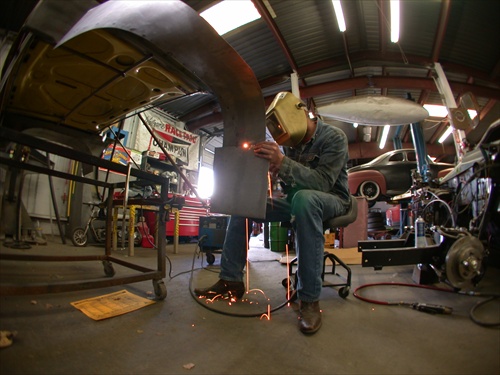
    He has wanted to build a truck like mine for years, so he was extremely excited to get the chance to sculpt out the body and pound out some fenders.
    He was going to build everything out of sheet metal, but that turned into a problem.
    The extreme angles needed to make the body look right made the use of all metal nearly impossible.
    So he is going to be using a mix of sheet metal and expanding hard foam to build the fiberglass mold.


    DSCN3798.JPG DSCN3787.JPG

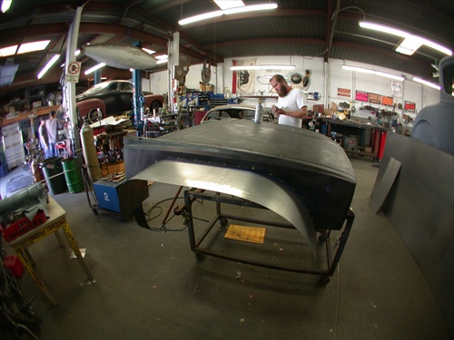
    The first thing I had them do was shorten the bedsides by 1 foot off the rear, no need for long bedsides.


    From there they have a free license to make the front end look correct.
    The front end will be widened by 20 inches with tire bumps and flairs. There will be a cowl induction hood designee built into it for clearance of the air intake system. The hood and fenders are going to be a 1-peace designee, with some small fenders, or splash grads. I will update things as we go.


    DSCN3797.JPG
    Last edited by camoit; 02-25-2012 at 12:02 AM.
    Members come and members go, But the board keeps track of them.
    Find me on FaceBook
    clicking HERE.

    Or look on YouTube Click Here.
    http://mobilemillwright.com

  11. #36


    Array
    Status
    Offline
    Join Date
    03-16-2011
    Posts
    3,823
    Location

    Sacramento, CA
    Vehicle

    1979 Dodge D-50
    Engine

    Chevy V6

    Foaming at the Mouth

    Now that Ben has an idea on how the front end will look he has decided to use foam in place of metal. Granted, they do extreme metal fabrication on the hot rods they build but there are just some things that would take way to long and too much money, like this car frame.

    DSCN3820.JPG


    So foam is a Farley inexpensive way to build a fiberglass mold. The first step was to build a dam out of cardboard all around the hood and fenders. Next comes the foam.


    Measure part A & B to 50/50 then mix for 10 seconds. After that, pour on the foam. This is hard foam. It is very, sticky so don’t stick your finger in it just to feel how soft it is. (Ben found out the hard way) NOTHING, and I mean NOTHING, will remove it, next to sand blasting.


    Once you have a nice thick even coating you must let it stand for about 30 minutes to harden up. After that you can remove the cardboard dam. Next comes the sculpting of the fenders. The hood has taken 2, two-gallon kits to obtain a thick enough coating to make the 2” cowl induction style hood and fender bumps.
    Please remember during an emergency the hood can be used as a flotation device in the event of a water landing.


    DSCN3842.JPG DSCN3837.JPG
    DSCN3839.JPG
    DSCN3840.JPG
    Last edited by camoit; 05-28-2011 at 07:20 PM.
    Members come and members go, But the board keeps track of them.
    Find me on FaceBook
    clicking HERE.

    Or look on YouTube Click Here.
    http://mobilemillwright.com

  12. #37

    Array
    Status
    Offline
    Join Date
    03-26-2011
    Posts
    409
    Location

    Portland, OR
    Vehicle

    1986 Dodge Power Ram 50
    Engine

    G54B
    LOL, love that stuff. Little foam mushrooms will sprout EVERYWHERE when you use it. Makes a God-awful mess, but damn it's fun. Interesting way to make the mold, very doable as well. Would have been cheaper (and likely safer) to use some kind of mother-mold and less foam. 1/4" plywood or scrap sheet would have done it well enough. Instead of being 2 feet thick, the cast woulda been half that or less.

    Time for lots of release agent and resin/fabric! If yer feeling insanely rich, ask about carbon fiber. LOL

    Yeah, the more I look at that, the more I see a huge waste of 2-part foam...these guys need to talk to Bill Owen or some of the other computer case modders out there. Even that thick that stuff is gonna be easy to crack and stupidly heavy. Bad tooling/engineering is bad. /shrug

    Edit: The English Wheel in post #30 is about enough to make me soil myself...../drool
    Last edited by Acuta73; 05-28-2011 at 11:33 PM.

  13. #38


    Array
    Status
    Offline
    Join Date
    03-16-2011
    Posts
    3,823
    Location

    Sacramento, CA
    Vehicle

    1979 Dodge D-50
    Engine

    Chevy V6
    The total weight of the foam is 35 pounds, across the substructures. That is the original hood and fenders. Inside of that is a complete structure that mimics the stock inner steel of the truck that the fenders mount to. As far as the hood and fenders are concerned they think they are still attached to the truck. Once it takes shape you will see. I can’t describe it. It’s a hybrid between the stock hood and this type of hood. But when it’s done there should only be about 10 pounds of foam left.

    kn_trophy_truck.jpg 05-26-11_1721.jpg

    Now if you need an Indy car body I met a guy that has the molds of some of the older models. I would love to have him make the parts for me but he is way, way out of my price range. But there is a guy here in Sacramento that builds Drag Racing boats that is willing to show me the ropes on vacuum bagging fiberglass.
    Last edited by camoit; 05-29-2011 at 03:12 AM.
    Members come and members go, But the board keeps track of them.
    Find me on FaceBook
    clicking HERE.

    Or look on YouTube Click Here.
    http://mobilemillwright.com

  14. #39


    Array
    Status
    Offline
    Join Date
    03-16-2011
    Posts
    3,823
    Location

    Sacramento, CA
    Vehicle

    1979 Dodge D-50
    Engine

    Chevy V6

    Body Test Fitting.

    Today I test fit the new body mold. Now you can see the shape of the hole truck. The front end will be cut from the cowling at a 45 degree angle to the fender. Soon it will be time to start the fiberglass. Once the foam is ready it will be covered with a fiberglass twill and resin. Then it will get bondo shaped then a full paint job. The better the finish of the plug the better the finish of the final part, but I'll get into that when the molds are started.

    Here are some pictures for you to look at. I want to keep the square look of the 80s, styling of the truck.


    The rear bed sides have been shortened by 12 inches, flared and cut to match the front end wheel clearance. You can also see the rear protection panel.


    DSCN3904.jpg DSCN3907.jpg


    This is the Point Of View from the driver seat.

    DSCN3906.jpg
    Members come and members go, But the board keeps track of them.
    Find me on FaceBook
    clicking HERE.

    Or look on YouTube Click Here.
    http://mobilemillwright.com

  15. #40

    Array
    Status
    Offline
    Join Date
    04-01-2011
    Posts
    155
    Location

    Garden Valley, CA
    Vehicle

    1990 Mitsubishi Mighty Max
    Engine

    6G72
    that thing looks bad ass!

  16. #41


    Array
    Status
    Offline
    Join Date
    03-16-2011
    Posts
    3,823
    Location

    Sacramento, CA
    Vehicle

    1979 Dodge D-50
    Engine

    Chevy V6

    The Fiberglass shop.

    I found a fiberglass guy that was willing to work with me. This guy has a crap load of body molds. Corvette, GT, Formula 1, Pro Stock, you name it. He has Formula 1 McClaren molds from McClaren them selves, from there first car, to the car of tomorrow (Shhhh). They are sending him the plywood shapes. Once I get a picture of it then you will see how to do a mold the right way. All I could say was Holey crap. It's nothing like you think..

    A Formula 1 wing,,, just the wing, not the mounting or anything will run you around $12000.00 just for 1 part. The process will be detailed later on in the build. It involves a Auto Clave type thing, and some large press type equipment.


    !cid__06-16-11_1346.jpg !cid__06-16-11_1348.jpg
    Last edited by camoit; 06-09-2019 at 05:12 PM.
    Members come and members go, But the board keeps track of them.
    Find me on FaceBook
    clicking HERE.

    Or look on YouTube Click Here.
    http://mobilemillwright.com

  17. #42


    Array
    Status
    Offline
    Join Date
    03-16-2011
    Posts
    3,823
    Location

    Sacramento, CA
    Vehicle

    1979 Dodge D-50
    Engine

    Chevy V6

    One of a kind, Composite Bodies

    Lets dive into the world of composite bodies. The man I found to build the body has been building composite bodies for years.


    Jeff currently has all but 3 F1 McClaren molds from the McClaren factory. He is expecting a prototype mold to arrive soon. I’ll get some pictures when it comes in. His main focus is in racing from the F1 to the GT car bodies.


    The first thing was to shorten the rear bedsides by 12 inches off the back end and build an under structure. Next was to cut the wheel opening to match the front.


    DSCN3894.JPG DSCN3914.JPG


    The front fenders and hood was welded together and a full under structure was built to hold the form of the stock shape. Next was to cover the whole thing with 10Lb foam. Then rough cut and sand to shape.


    DSCN3891.JPG


    When building the plug, it is important to avoid sharp edges. If the plug has sharp edges then you may have problems with the first covering of fiberglass when making the hard shell. If the edges are to sharp then the glass can bunch up and not lay flat where you want it.


    Next is to fill the large air pockets on the foam with some bondo. This will reduce the possibility of the mold generating air pockets from heat.


    DSCN3939.jpg


    I plan on having louvers in the hood. They will be cut into the part after it is built. It’s easier to cut them in later because they take so much time. When working with the resin and fabric you need to keep things moving and not stop.
    The louver plugs are from a Chevy Camaro.


    DSCN3961.jpg


    Next up will be the building of the mold and the final body work.

    Last edited by camoit; 06-09-2019 at 05:13 PM.
    Members come and members go, But the board keeps track of them.
    Find me on FaceBook
    clicking HERE.

    Or look on YouTube Click Here.
    http://mobilemillwright.com

  18. #43

    Array
    Status
    Offline
    Join Date
    03-26-2011
    Posts
    76
    Location

    KY
    Vehicle

    1990 Dodge D-50
    Engine

    G54B-T
    Nice.

    Are you planning on selling any kits? To bad its not for a 2nd gen.

  19. #44


    Array
    Status
    Offline
    Join Date
    03-16-2011
    Posts
    3,823
    Location

    Sacramento, CA
    Vehicle

    1979 Dodge D-50
    Engine

    Chevy V6
    Quote Originally Posted by turbomax View Post
    Nice.

    Are you planning on selling any kits? To bad its not for a 2nd gen.
    I don't think there is much difference between the first gen and second gen body's. I guess I can take a peace of cardboard and draw out the curves and see how close it would be. The stock lines fade out fairly quickly on the bed sides. They have a built out flair of 7 inches on them. The front flairs are 10 inch. I will have the tooling to build more as needed. Once I have that the bed sides are going to be around $450 each to have produced with the gel coating. I would be more than happy to let you contact my fiberglass guy and you guys can work out the pricing. It should be a couple more weeks and the molds will be done. The tooling and first run of parts will be somewhere around $7000 to build. A one off body is big bucks to produce. But in the end I think it will be worth it because it's just that. One of a kind.
    One thing is there is no fuel door anymore and the wheel wells are opened up, big time.

    Looking at More of a RE-build Thread the body's look fairly close.
    Last edited by camoit; 07-28-2011 at 09:49 PM.
    Members come and members go, But the board keeps track of them.
    Find me on FaceBook
    clicking HERE.

    Or look on YouTube Click Here.
    http://mobilemillwright.com

  20. #45


    Array
    Status
    Offline
    Join Date
    03-16-2011
    Posts
    3,823
    Location

    Sacramento, CA
    Vehicle

    1979 Dodge D-50
    Engine

    Chevy V6

    Building the class A mold and plug.

    Willie has finished the bodywork on the rear bedsides.


    After the hard shell was placed on the foam it was covered with a black 2-part feather fill primer.
    This makes it possible to see all the imperfections of the hard shell.
    Next comes a skim coat of Bondo.

    DSCN3990.JPG

    The Bondo was applied and worked in sections. This is done so the lines of the body are not lost.
    Now the Bondo is rough sanded down so the hard shell and black just shows through the Bondo.

    DSCN4019.JPG

    Now the lines can be squared up using masking tape.
    The tape makes a nice straight line. You sand the curves out until you just hit the tape.


    After the body is fully sanded another coat of gray primer is placed on the plug, blocked and wet sanded to get the final body lines. Then one more coat of the black 2-part feather fill primer is applied. Once cured the primer is buffed smooth to a glass finish. The smother the finish the better the part will come out.

    DSCN3993.JPG DSCN3995.JPG

    This is referred to as a class A plug and mold. Next the plug is prepped for the mold. The first thing is to put on a good coat of Partall Paste #2 Release wax on the plug. Do Not Use a carnuba wax, you are asking for trouble. It can’t take the heat that is generated by the resin. It can reach temperatures of 130 degrees. Next you can tape on card stock paper flanges to the plug. The flanges will make it possible to remove the mold from the part and give the mold a back flange that gives the part it’s strength. The last step before the fiberglass is a thick coating of tooling gel. Tooling gel is a harder gel coat then what is used for the part. Once the fiberglass is applied to the plug it will bond to the gel coat. After removed from the plug it will be absolutely smooth just like the plug was. Next comes the building of the part itself.

    DSCN4051.JPG DSCN4059.jpg
    Last edited by camoit; 06-09-2019 at 05:14 PM.
    Members come and members go, But the board keeps track of them.
    Find me on FaceBook
    clicking HERE.

    Or look on YouTube Click Here.
    http://mobilemillwright.com

  21. #46

    Array
    Status
    Offline
    Join Date
    04-28-2011
    Posts
    111
    Location

    Lewistown, PA
    Vehicle

    1984 Dodge Power Ram 50
    Engine

    Dodge V8
    This thing is a work of beauty, I'll be in touch with you about ideas/info for my own off-road 1st Gen D50 too.

  22. #47


    Array
    Status
    Offline
    Join Date
    03-16-2011
    Posts
    3,823
    Location

    Sacramento, CA
    Vehicle

    1979 Dodge D-50
    Engine

    Chevy V6
    Members come and members go, But the board keeps track of them.
    Find me on FaceBook
    clicking HERE.

    Or look on YouTube Click Here.
    http://mobilemillwright.com

  23. #48


    Array
    Status
    Offline
    Join Date
    03-16-2011
    Posts
    3,823
    Location

    Sacramento, CA
    Vehicle

    1979 Dodge D-50
    Engine

    Chevy V6

    The D50 line

    Just thought I would toss up 2 Pict's of the hood plug and the ever so important hood line being put back in. It was lost under 2 inches of foam and 2 layers of fiberglass. It should be ready for a buffing this weekend. Then it's mold time.

    Members come and members go, But the board keeps track of them.
    Find me on FaceBook
    clicking HERE.

    Or look on YouTube Click Here.
    http://mobilemillwright.com

  24. #49


    Array
    Status
    Offline
    Join Date
    03-16-2011
    Posts
    3,823
    Location

    Sacramento, CA
    Vehicle

    1979 Dodge D-50
    Engine

    Chevy V6

    Electrical System is Done..

    I just finished up the wiring. After 6 months it is finally finished and tested. I would work on it here and there when I received the parts. The final part that was holding me up was the intercom system.

    Before and after pictures. Main board before the clean up.

    09-25-11_1725.jpg 09-27-11_0001.jpg
    Wiring harness before the final clean up, and after. Now it looks like a real harness.

    Members come and members go, But the board keeps track of them.
    Find me on FaceBook
    clicking HERE.

    Or look on YouTube Click Here.
    http://mobilemillwright.com

  25. #50


    Array
    Status
    Offline
    Join Date
    03-16-2011
    Posts
    3,823
    Location

    Sacramento, CA
    Vehicle

    1979 Dodge D-50
    Engine

    Chevy V6

    Building the class A mold part 2

    How to build the mold.

    The very first and most important thing is to wax everything. And I mean everything including the paper you will use for the flang of the mold. Use the correct wax Partall Paste #2 Release Wax is the recommended wax. Then over the top of that you apply a coating Partall #10 Release PVA Film.


    Next is to mark and cut the flange paper. It’s a good quality smooth card stock. You can get it for free if you hit up the local print shops around town. They normally just toss out the scraps, so it’s in your favor to ask them about getting the leftovers. Mark the paper with a marker and cut to fit. Make the fit as tight as you can.

    DSCN4161.jpg


    Things to look for when determining how and where to put a flange. The first thing is to look for is what is called a “Lock Up” This is a place the where the plug turns back on it’s self. Take a look at the front fender of your truck. The lock up area starts near the bottom. If you were to just cover the hole thing with glass and resin the plug would never come out of the mold, so you make a flange near that area out of the card stock. Keep in mind you want the plug to come out of the mold as easy as it can.


    Once you have the plug flanged completely it is now ready for the tooling gel coat. You can spray or brush it on; it’s up to you. Cover only the plug and flanges within the first area you plan to work. This is the area before the lock up. Allow the tooling gel coat to dry over night.

    DSCN4196.jpg


    NOTE; Pre fit everything.
    Now you can start the fiberglass lay out.


    DSCN4215.jpg


    Look out for tight areas where material can bunch up. Make as many relief cuts as necessary to allow the fiberglass to lie down on the plug and go over sharp bends and around corners.


    Use as large of a peace of glass as necessary to cover an area. Don’t try to cover the whole thing in one try. This would cause the material to pull away from the areas you have already covered earlier. The stranded fiberglass mat is not as flexible as the glass cloth you will use later on. The mold will get a total of 4 layers of fiberglass, 2 of the multi directional mat and 2 layers of cloth.


    Now you can apply the first the resin coat over the gel coat. Work in small areas so you can keep the areas wet. If you take too long on one area then you run the risk of the resin drying on you. Work fast you have about 45 minutes if the air tempters under 65 deg. Now you can stick on the first layer of mating.


    DSCN4213.jpg DSCN4212.jpg


    Then cover it with more resin pushing the mating down around the corners and edges. It’s best to have 2 people if working large parts. One person applying the resin and matting while the other works the roller removing air bubbles and working the matting into the corners.


    DSCN4230.jpg DSCN4207.jpg DSCN4220.jpg


    Overlap the matting about 1 inch. It should overlap like shuffling a deck of cards. Once you have worked back to the peace you started with you can start the application of the second layer of matting. Then more resin, and more rolling. Once you have covered and rolled the whole area including the flanges with the 2 layers of matting you can now apply 2 layers of cloth. It will be the same process but you should not need as much resin. Remember be careful when rolling not to pull the material. The cloth should not need as many relief cuts if any. It is more flexible and now the sharp corners are covered the whole thing is thicker and flatter. Work fast keeping things moving forward. The 2 layers of cloth go right down just as soon as you have covered the area with the matting. No stopping, no breaks, just go, go, go.

    DSCN4250.jpg DSCN4247.jpg


    Now you can have a beer because you are done for a couple of days. Let it out gas for at least 48 hours before removing the paper flanging you made. In the mean time you can start to make the last set of flanges for the “Lock Up” areas. After removing the paper be sure to wax the new fiberglass flange areas. Otherwise the mold will never come apart. This will be covered in step 3 and 4 later on.


    DSCN4253.jpg DSCN4257.jpg DSCN4260.jpg
    Last edited by camoit; 06-09-2019 at 05:16 PM.
    Members come and members go, But the board keeps track of them.
    Find me on FaceBook
    clicking HERE.

    Or look on YouTube Click Here.
    http://mobilemillwright.com

Page 2 of 7 FirstFirst 1234 ... LastLast

Tags for this Thread

Bookmarks

Bookmarks

Posting Permissions

  • You may not post new threads
  • You may not post replies
  • You may not post attachments
  • You may not edit your posts
  •