I have not seen his build thread yet, will have to try and find it.Originally Posted by geezer101


I have not seen his build thread yet, will have to try and find it.
Except I have a 2.4 and a 4 link in the rear
This piece ends up being the runner that feeds the wastegate from the collector. It required way more grinding on the right side to get it to mate properly. To make the hole in the collector I used my plasma cutter, then cleaned it up and opened it up the last little bit with the carbide burr on the die grinder.
Wastegate mounted and also made a quick downpipe. The 3" downpipe fits but it doesn't leave much room between the frame where the idler arm is and the trans bellhousing, so next time I pull the trans I am going to clearance the corner of the bellhousing just to try and prevent any rattles.
My coolant pipe that goes from the thermostat to the upper rad connection. Some stainless 316 tubing from an old valve at work that we recently replaced and had to retube with larger tubing.
This is with it in place. I do want to make some little tabs yet to secure it to at least one of the valve cover bolts, mostly to prevent any rattles. It most likely will absorb some of the radiant heat from the header, but I dont think it will get too hot for the rad to handle, most of the heat should be by the collector?
FIC 1200 cc injectors, if these are not enough I do have an older set of 1600's just in case.
Cleaned up the old FIC fuel rail too
Put the Kiggly Racing head oil pressure regulator in.
Tomorrow I hope to get the starter to fit, intake on, and wastegate tied into downpipe. Then try my luck again at aluminum welding. I really want to put the throttlebody on the outlet of the FMIC for 2 reasons. One is because its under the battery tray and I will be cursing myself when trying to bolt it up, but its out of sight. And two because then the elbow wont be right behind the rad fan. Its drive by wire so the throttle cable length or placement wont be an issue.
I don't have any updated pictures of it but I did manage to complete the driverside intercooler piping with the throttlebody located below the battery tray. I did trim the tray down and make it so I can access it though. Also had to trim the lip on the fender right below the tray up to the upper control arm, it was in the way of the intercooler pipe. I can totally see why a FMIC with a lower outlet port would be beneficial for piping routing, its pretty tight for me.
The passenger side intercooler pipe is simple, just one bend to make, still have to plumb the wastegate outlet over there too.
The starter issue has also been resolved, trimmed the shim with the pneumatic body saw. Tried for a few hours to get better at aluminum welding but had no luck. I can get a puddle, but most of the time the filler melts before I get it in the puddle. Another time perhaps, pretty sure my issue is me not pulling the filler out enough so its relatively hot before I even try and dip it in.
This is showing the lip on the inner fender that I had to trim for the intercooler pipe, also trimmed down the battery tray. The battery still fits fully on the tray. Perhaps in the future it will be relocated but for now this works fine.
This shows the intercooler pipe on the drivers side. Its tight, a lot of bends, and the DBW throttlebody is mounted on the intercooler outlet. The combination of bends and couplers should allow enough flex to not tear or break anything when the motor torques up, I couldn't really see another way of doing it with this intercooler and intake.
Overflow jug is now relocated for easier plumbing. Hopefully nobody mixes up the fluids between these two jugs haha.
Fuel pressure regulator location. I would have ran the hoses for it but I need to get one 45* hose end for the inlet to it. Still need clean the fender below it, its nasty.
Catch can locations. No room for a drain to be plumbed in, but there is enough room to unthread them and empty the bowls. I really like the design of these cans over what I had in the BMW, these have threaded dipsticks in them to check the levels.
Downpipe to the flex joint and flex joint to the first piece of exhaust pipe that runs to a resonator.
Its pretty tight in there for a 3" exhaust but it shouldn't rattle.
Just beyond this picture is the resonator, and I stopped for the day with the exhaust at the back of the cab... my saw blade bit the dust, broke a tooth off a spit out the cut off piece. Time to get a new blade. (You can also see that I haven't finished the trans mount, need to drill 2 holes and bolt it up.)
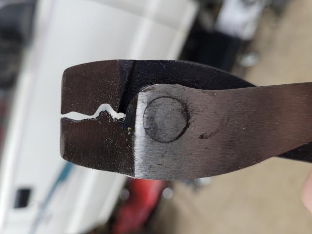
Bought a set of wire cutters and crimpers with long handles at Princess Auto the other day for the purpose of making a bead forming tool. I cut the wire snips off the tip, used the grinder to also round off some of the other edges in the groves. It works pretty well but I wouldn't want to put a lip on a full car build haha. I only needed to do a few fittings as the others I used already had lips on them. FYI, if you do this, don't go full send on the handles the first time around, it can poke through the tube material. I went one time around the tube going about half way then the next time around I went to the point I was happy with.
Whoa, hold up. You mounted the throttle body on the intercooler? I've never heard of it being set up like that before. And that is not a transmission mount - that is an integrated frame rail brace. This thing is being built like a tank! You're using some very unique lateral problem solving design principles.
Geezer approves
haha thanks. I built a X cross brace under my LS3 swapped BMW before to help with chassis flex, kind of had that idea when building this trans mount. Figured integrating the trans mount and driveshaft loop together would help to stiffen things up a bit. It can't hurt. Was also debating on running a 1.25" or 1" piece of tubing from the front edge of the lower portion of the chassis 4 link mount up to the back side of this x brace thing, not sure if its going to be a noticeable change if I do i though.
As for the throttlebody on the intercooler, if anything I can see some possibly idle control issues but doubt it? Just trying to think of any issues and really its maybe a cubic foot or so of volume?
neither will help a street Mmax go any quicker, @6000+ rpmExcept I have a 2.4 and a 4 link in the rear
more or less.... like solutions, looking for a problem. No principles. Throttle bodyYou're using some very unique lateral problem solving design principles.
no chassis flexing in the plane that x-brace offers strength/is laid out. Weak vertically
colt likes to build stuff. Has the means, all the toys & big balz. Heck of a truck in the making
Totally understand the 4 link not serving a purpose after the first 60 feet, but having more options to adjust things to get traction and prevent wheel hop/spin will be nice. Previously I found it hard to get past the 1.7 in the 60 foot as I was either fighting wheel hop or spinning, I am sure in that case being a standard and not wanting to slip the clutch much probably didn't help the situation.
The stiffening of the chassis vertically should come in 6 months or so when its winter, just doing what I can for now.

wow nicccccc
Its been a while since I updated this. I did get it on the road this summer, late in the season but it was on the road. No races for it this year. I got tired of the oil pan that was in there slowly seeping oil out of the flange for the turbo oil return line and a few other random places that I tried to fix, so I drew up and had some stuff cut, now the pan has a better baffle and more capacity, better turbo oil return location, plus no leaks. Was welding it on an old spare block I picked up from the wreckers.
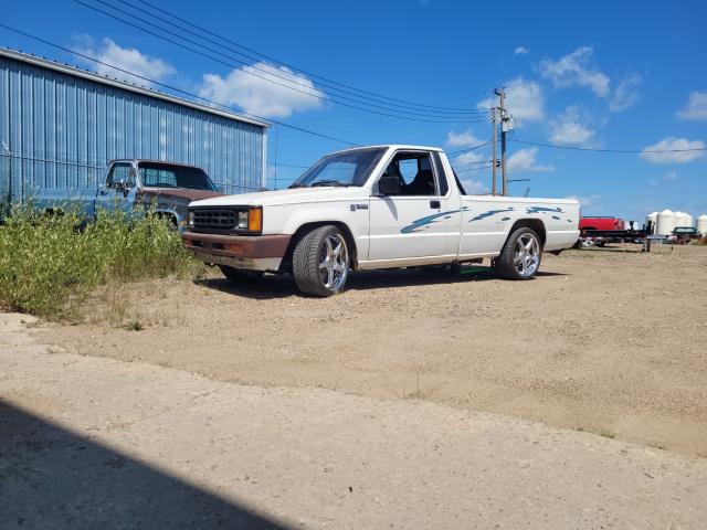
First trip out of the shop. Had some magnetic trailer lights hooked up for brake lights.
I didn't like the performance of the rad fans that came on that rad from the talon, they didn't cause anything to overheat but once they would come on it would they would pretty much stay on until the vehicle was moving, and this was only in maybe 75-80* weather. They are 12" fans, but they just didn't move much air. Comparing them to the SPAL fans I replaced them with, the SPAL weight is considerably more but at least they flow lots of air now. (SPAL fans on the bottom)
Hooked up and ready for the dyno. I wanted to leave the box off for the dyno just so the oil coolers would at least have some air flow. The oil temps were good while on the dyno, so the next test is when the box is on and driving in town I suppose. I had an injector fail a few weeks before the dyno so I had the shop install a set of 1700s in it as thats what they suggested to match the turbo capabilities. It made just under 350 hp and 325 ft/lbs at 4500 rpm at wastegate pressure (14 psi). Need to finish hooking up the boost control solenoid then start turning up the boost.
Then in the following week after the dyno the headgasket started to leak. In hindsight, I should have probably pulled the head off and checked it. Turns out the previous person who built the engine used a straight up copper gasket and didn't cut the grooves in the block for the wire, so it was pretty easy for it to leak. Two studs were also not installed properly I think, one was super tight and the other not at all, none of them had washers under the nuts. Oh well, nothing damaged other than the gasket.
I just finished putting the new mls headgasket on today and setting the timing again. Did a 3d scan of the lower timing cover because the portion of mine that indicates the timing is damaged. I want to try and draw something up and print it to indicate timing better if this one ever totally fails. I haven't tried printing anything that is capable of that kind of heat yet but its something to look at in the future.
In the next few weeks, get a rad cap installed on the rad, wire up the can bus expander and fuel sending unit, get the box bolted down (its currently sitting on blocks on the frame).
I put the new head gasket on it last fall then started tearing into the inside of the truck to build the roll cage. 6 point cage with removable door bars, most of it tig welded. Did the tig because its easier to weld upside down in some spots and can get into smaller/tighter areas. I couldn't move the b-pillar hoop further up unless it came forward at the same time. Because of this I had to notch into the window frame which I was hoping to avoid but it all worked out and fits.
I did fill in all those holes in the box with the original pieces. The extra ones on the drivers side are from the previous owner trying to locate the fuel pump when it was changed... The black box in the front of the box is the new power steering reservoir. Just below that box is an electric power steering pump from a mini-cooper. Currently its wired up to a solid state relay, but nothing triggers it yet. Was hoping to have the ecm control it to automatically turn it on/off but haven't got that far yet. All the lines are hooked up.
Because of the cage I relocated the HVAC blower. Drew up this piece and 3D printed it. Blower resistor is mounted in it still. Pretty much the only time this will be used late in the evenings in the early spring/late fall. This locates it just behind the glovebox on the left side.
Made an aluminum plate and mounted it below the dash, it contains the fuse panel, terminal strips, extra relays and the MPI relay is mounted on the back side. I have cleaned up the wires a bit since this picture, but it still needs more attention.
After doing the cage and cylinder head the truck didn't want to start last week. 2 problems were found. The starter wouldn't even attempt to move if the voltage to it was much below 9 volts while attempting to crank. During cranking I still had 11 at the battery but less than 9 on the small wire feeding the starter. So I just wired in a new relay instead of tearing into the harness to find a possible bad connection or relay, I know its not ideal, but left the old wire abandoned in place. The other problem found was that the power transistor unit had failed. Open circuit with power applied and 1.1M ohms with 1.5 volts across the transistors. The manual says it should be closed when power is applied not open... and the 1.1M ohms is probably way too much. So I swapped over to a coil on plug setup and made a mounting plate for them. They are Denso coils from a Toyota Echo haha, they fit, can be wired directly to the ECM and I did find the dwell settings online for them. Added 2 wires for the 2 extra coils and updated the settings in the ECM to drive 4 coils directly and not 2 in wasted spark mode.
Took the truck out for a drive today for about an hour. Need to adjust the front shocks, there is currently 0 dampening on them and the truck kind of floats around. Also, I have a small coolant and oil leak on the front lower section of the engine. All waterpump hoses and connections are dry, same with oil cooler fittings. Oil pressure regulator is wet, same with bottom front area of engine. Guessing the coolant is from the waterpump to block gasket and oil is either from pressure regulator spring housing, or front main seal... So the truck went back on jackstands a few hours ago and needs some disassembly to further inspect.
So I fixed the major oil leak, it was coming from the one balance shaft delete that was done on the motor. It still leaks a bit from the pan, but I plan on making a different one eventually. I put heavier springs in the rear so it had more usable suspension, at least now a full tank of fuel wont make it sit noticeably lower. I do want to drop down the lower shock mount an inch or so to level it out some as I think it still sits high.
A few weeks ago I changed out the alternator. I haven't been driving it much this summer because after about 10 minutes of driving the stock alternator would not be able to keep up and the voltage would be around 12.6 volts with the headlights unplugged and power steering pump turned off. So now it has a Saturn alternator on it, made a bracket to attach it to the drivers side of the engine. Now it maintains 14.0 volts with the headlights, 4 fans, power steering pump and fuel pump on at idle in gear. Its great now.
I found that the A shift solenoid was failed (leaking) and it was preventing it from going into first gear but would go into fourth. This I am sure was an issue since the start because now that the solenoid is changed out the truck actually is half decent from a dead stop, plus the trans temps usually stay below 210* now.
Not much else to add yet, going to try and get some videos of it here soon.
 Posting Permissions

 Reply With Quote
Bookmarks